Product Overview
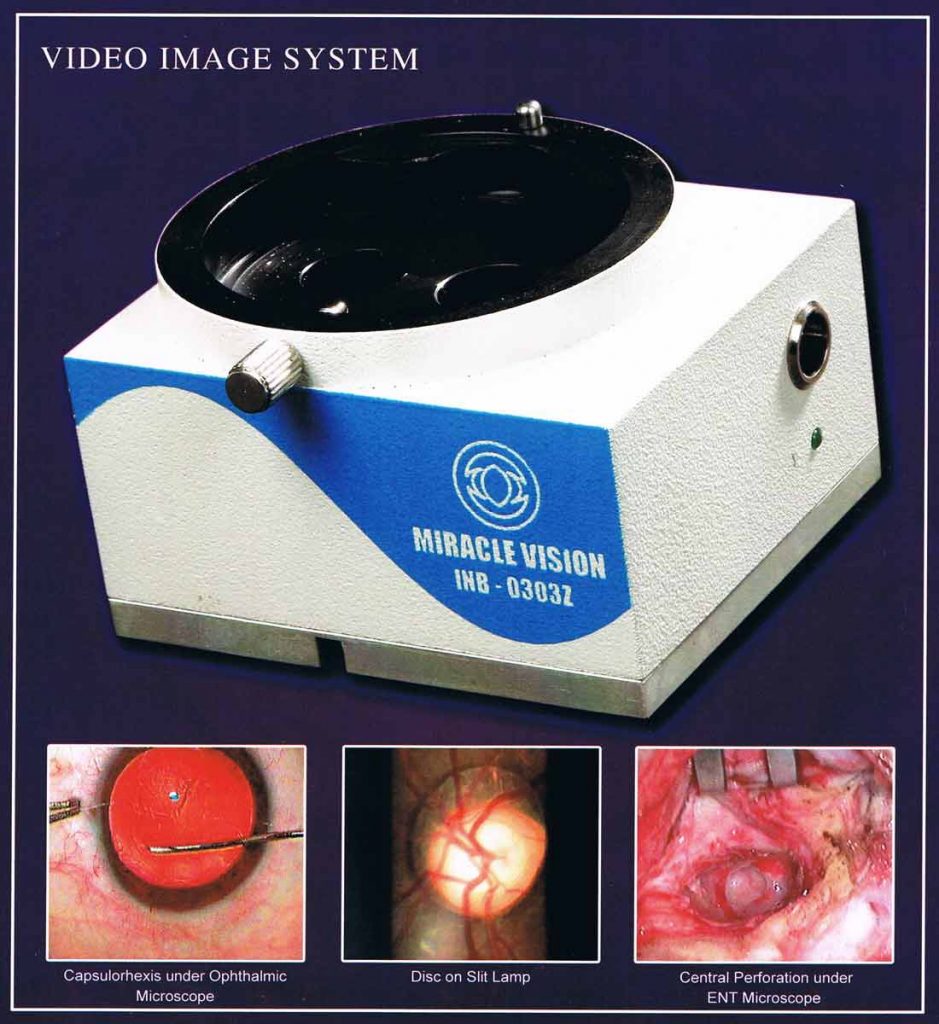
Inbuilt CCD Live display System Model INB-0303-z
Introduction
This Instrument is used to display the live surgery and diagnostic pictures on TV / Computer Monitor for academic purpose / patient’s relatives to explaining the details.
This Instrument features are following.
-
- No Beam splitter, So no illumination loss
- Compact in size (85mmW x 72mmD x 52mmH)
- Sony CCD module
- 90 % field of view on monitor #
- Light weight (390gms, No harm to arm of compact microscopes)
- Universal adopter for most of the Microscopes and Slit lamps
- Single wire socket, so no congestion of wires
- High Resolution Picture Quality
- No Disturbance on Binocular Vision
This instruction manual covers an over view of the basic operation, trouble shooting and maintenance. Keep this manual at hand for future reference.
Precautions
- Since this product is a precision optical cum Electronic instrument, always use and keep it in a normal environment and appropriate humidity level.
- When not in use, switch off the power source.
- For best result, use high quality output video cable (~75ohms) and use video amplifier for (more than 10mtrs) distance display / more than 2 monitors.
Installation
- Firmly hold and remove binocular part of Microscope/Slit lamp carefully by unscrewing the clamping knob and keep aside.
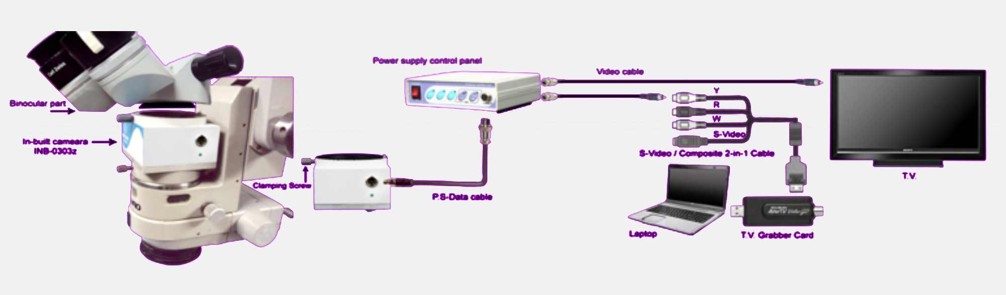
- Place an in-built Module INB-0303-z on Changer part of Microscope/Slit lamp with locating pin guided on locating slot and fasten the clamping screw of changer part.
- Place binocular part of Microscope/Slit lamp on In-built female slot with locating pin guided on slot and fasten the clamping screw of INB-0303zx.
- Connect PS-Data cable with INB-0303zx and Power module as shown in figure.
- While removing PS-Data cable from INB-0303-z, press and hold the button on 5 pin connector and pull it out. Do not pull by the cable as it may leads to malfunctioning of the camera.
- Connect V.cable with rear panel of power module and TV (AV in) / Computer Monitor*.
- Connect the plug into Main Supply (110v ~ 270v).
Operating Instructions
- Switch on the main power supply and switch on the power module.
- Green LED glows on In-built module and the objects under the focused microscope / Slit lamp are seen on the monitor.
Control panel operating instructions
- Menu switch is used to open the menu like Exposure, ATW (White balance), BLC, Contrast, Brightness, etc.
- Up / Down keys are used to select submenus displayed on screen.
- Left / Right Keys are used to increase or decrease the values of corresponding submenus
Camera Technical Specifications-Miracle Vision(Model-0303z)
| Name | Description |
|---|---|
| Chip | Sony Super HAD |
| Sensor Size | 1/3” Interline transfer color CCD sensor |
| Resolution | 620 Horizontal TV Lines |
| Scanning System | 325 lines, 50 fields / sec |
| Total Effective Pixels | 290 K |
| Minimum Illumination | 0.3 Lux of F1.2 |
| White Balance | Auto trace white Balance / Set Mode, ATW1, ATW2 |
| Gain | Auto Gain Control Min/Max |
| Iris | Auto Electronic Iris /Manual Iris |
| TV System | PAL |
| Power Supply | 12v dc |
| Current consumption | 200ma |
| Output | Video output at 75 ohms |
| Module Dimension | 85 x 72 x 51(mm) |
| Module Weight | 390g |
*As the video output is composite signal O/P, displaying on Computer monitor, editing, still photo capturing, editing and storing in CPU or Laptop are possible only through a digital conversion devices like TV tuner cord, Video grabber cord.
Product Details
Date: December 12, 2017
Tags: EyeCare